ME 158 Portfolio

Lab 1/2
This lab exercise introduced us to setting up work offsets in the machine and manually jogging the spindle to drill holes. I first faced off 0.05” from the top and then moved the spindle to each hole location to drill.
Lab 3
Similar to lab 1, this lab involved taking work offsets, but all operations were programmed using VPS. I used VPS to first face 0.05” from the stock and then programmed a pentagonal hole. The graphics mode allowed me to check my pattern to ensure it was set up correctly.
Lab 4
In this lab I manually wrote G-code to cut a square pocket. Because the tooling only consists of an end mill, each corner must contain a curve. After the cutting, I used a metal go-no go gauge to check if the dimensions were correct. Unfortunately in this instance I had used a 3/16” end mill instead of the 1/4” end mill I originally wrote my code for, so my part did not fit the gauge.
Lab 5
This lab involved the use of a pen plotter attached to the spindle, instead of a machine tool. In Homework 1, we manually wrote G-code that would spell out UCSB when plotted. The first part of this lab involved loading in G-code that would give the template, including the outside border and the caption at the bottom of the page. Once this was plotted, we loaded in our own code from the network drive to plot on the page. As can be seen, I didn’t have the best command of circular interpolation when I wrote the plotter code, so my curves are larger than necessary.
Lab 6
In this lab, I wrote G-code manually again to cut a frame, a pocket, and a boss. This program made heavy use of circular interpolation to form the corners of the frame and the 2.5D features. I had an issue with my work offsets here, which is why the features are not fully on the face of the part.
Lab 7
Lab 7 was the first time we were able to use HSMWorks to generate code for a part, as opposed to writing it manually or using VPS. This job involved facing, 2D pocketing, 2D adaptive clearing, and drilling. I had challenges finding the right operation for each step mentioned in the homework, but stock simulation and changing settings like stepover and stock to leave helped me achieve the right toolpaths.
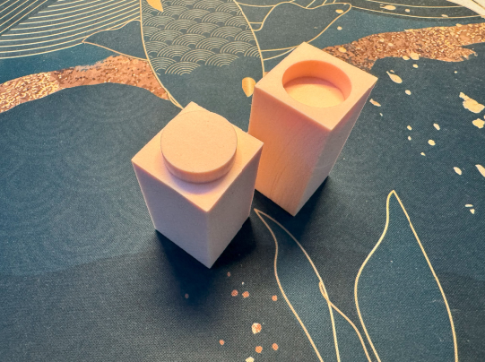
Lab 8
In the final lab, we used HSM to make a pin-and-hole assembly. Both parts were first faced and then I used adaptive clearing and pocketing to create the mating features. As shown in the photo to the right, the parts mate with a tight fit.